

This heart beat sensor is designed to give
digital output of heart beat when a finger is placed on it. When the heartbeat
detector is working, the top-most LED flashes with each heart beat. This
digital output can be connected to micro controller directly to measure the
Beats Per Minute (BPM) rate. It works on the principle of light modulation by
blood flow through finger at each pulse.
Digital Heart Beat Sensor:

Features
- Heart beat indication by led
- Compact size.
- Total heart beat count can be obtained serially every minute.
Applications
- Digital heart rate monitor.
- Bio-feedback control of robotics and applications exercise machines.
Using The Sensor
- Connect regulated DC power supply of 5 Volts. Black wire is Ground, Next middle wire is Brown which is output and Red wire is positive supply.
- Place the finger on the marked position, and you can view the beat LED blinking on each heart beat.
- The output is active high for each beat and can be given directly to microcontroller for interfacing applications.
Working
The sensor consists of a super bright red LED and
light detector. The LED needs to be super bright as the maximum light must pass
spread in finger and detected by detector. Now, when the heart pumps a pulse of
blood through the blood vessels, the finger becomes slightly more opaque and so
less light reached the detector. With each heart pulse the detector signal
varies. This variation is converted to electrical pulse. This signal is
amplified and triggered through an amplifier which outputs +5V logic level
signal. The output signal is also
indicated by a LED which blinks on each heart beat.
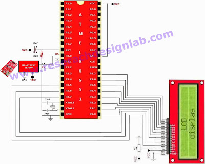
ATMEL SCHEMATIC:
ATMEL CODE:
For a sample code please Click Here